Hello everyone.
With the preparation done, it's time for the tappet (valve) clearance adjustment itself. This is on my Honda XR250 BAJA (the Japan-market XR250 / MD30); the engine is the same as the standard XR250 (MD30), so the procedure applies to that too. For other XR250 models, check the specified clearances in your own service manual.
The rough flow is as follows.
- Bring the piston to top dead centre (TDC) on the compression stroke
- Remove the valve hole caps and measure the valve clearance
- If the valve clearance is out of spec, adjust it
- Refit the valve hole caps, fuel tank, seat and so on
First, you need to turn the crankshaft to bring the piston to top dead centre.
To do that, remove the crankshaft hole cap and the timing hole cap.
The timing hole cap has a 6 mm hex socket and the crankshaft hole cap has a 10 mm hex socket.
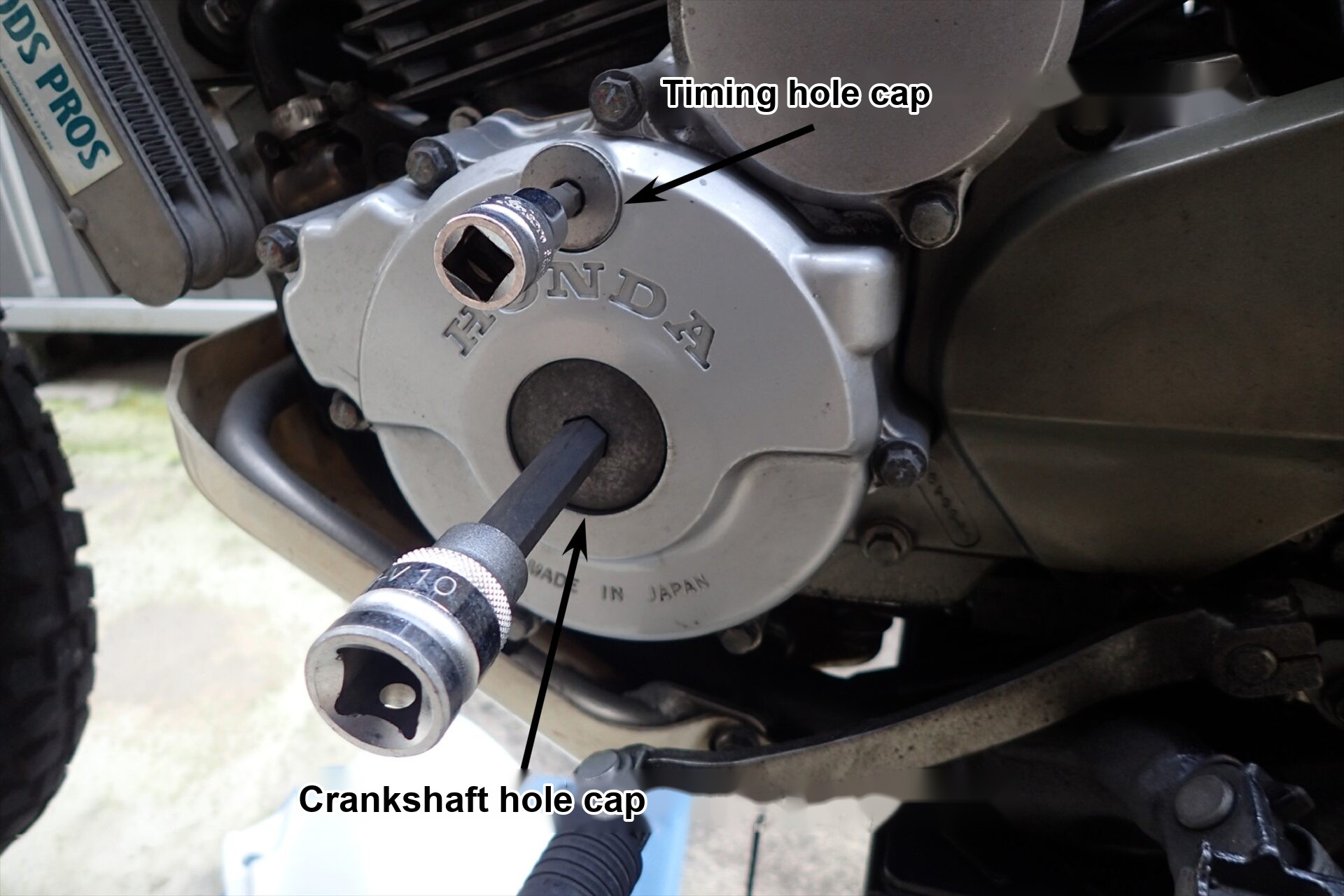
I took this photo with the sockets in place.
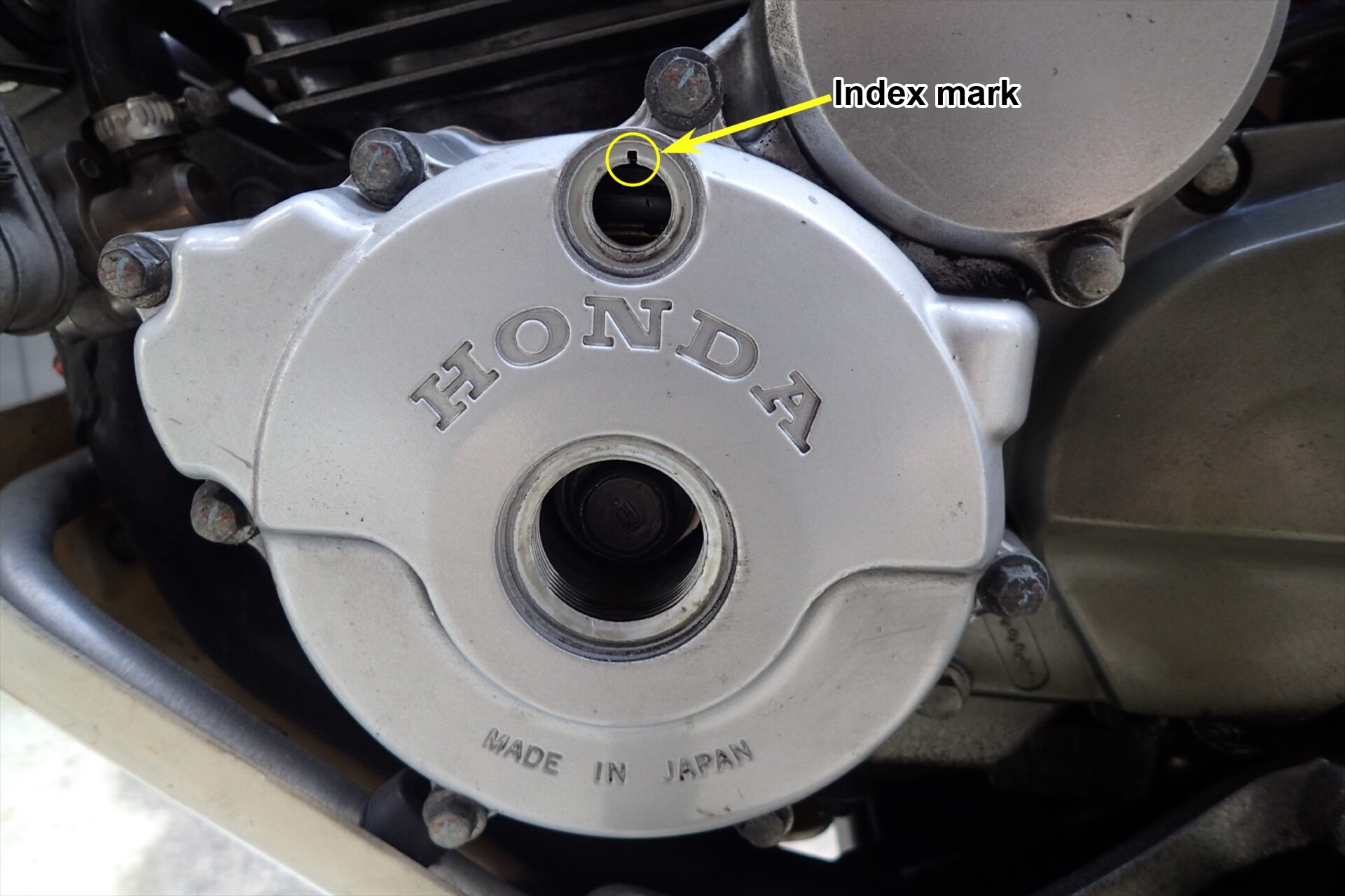
Here both caps are off.
There is an index mark in the timing hole.

You can turn the crankshaft by turning the 17 mm bolt inside the hole.
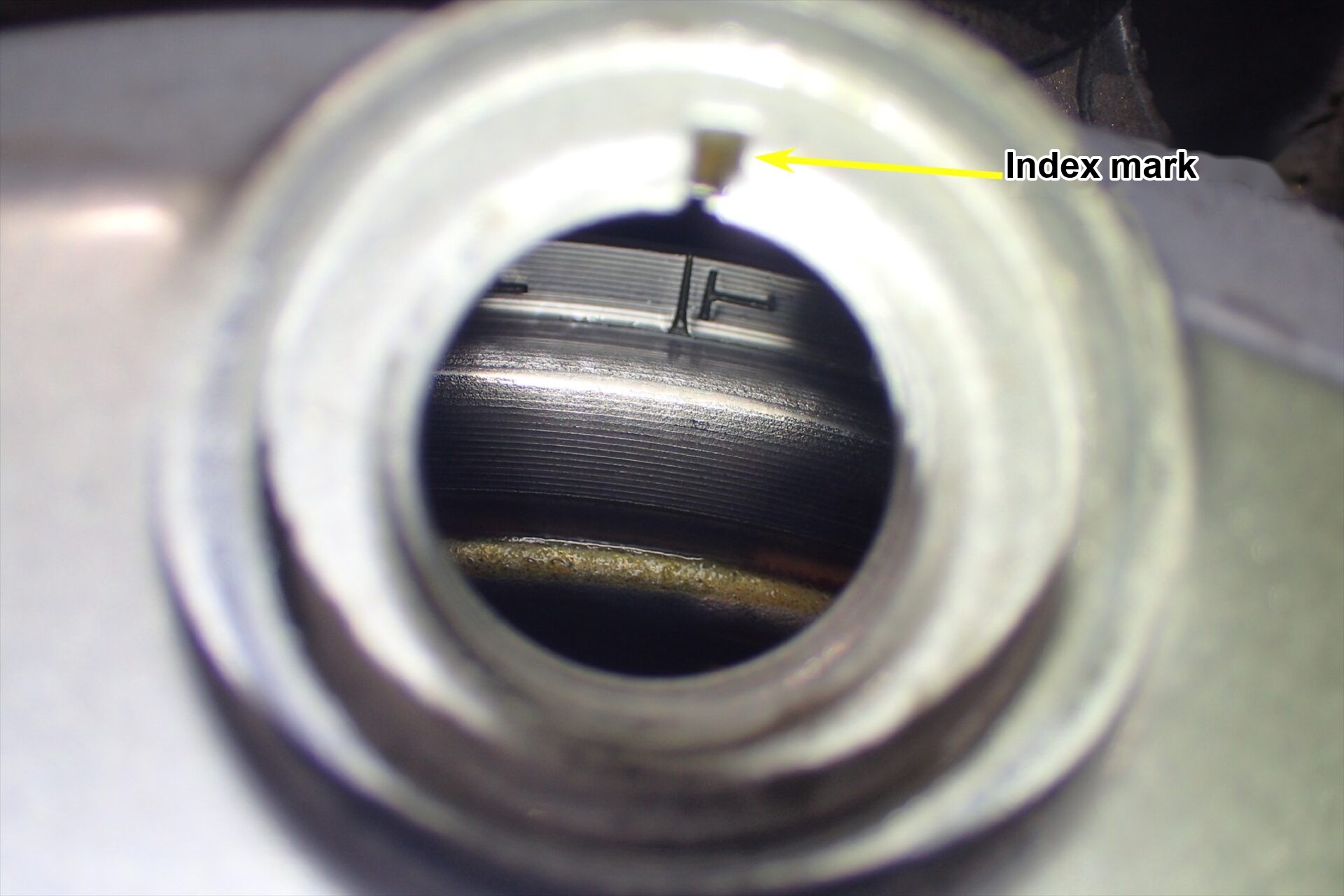
Now turn the crankshaft anticlockwise (counterclockwise) and line up the T mark on the flywheel with the index mark to bring the engine to compression top dead centre.
By the way, top dead centre is the point where the piston is at the very top of its travel.
A four-stroke engine completes one cycle every two turns of the crank, so there are two top dead centres in each cycle: one is exhaust TDC and the other is compression TDC.
To check whether the T mark position is compression TDC, line up the T mark with the index mark and then rock the crank back and forth slightly; if the rocker arms don't move, you're at compression TDC.
With that done, the next step is to remove the valve hole caps on the top of the engine.
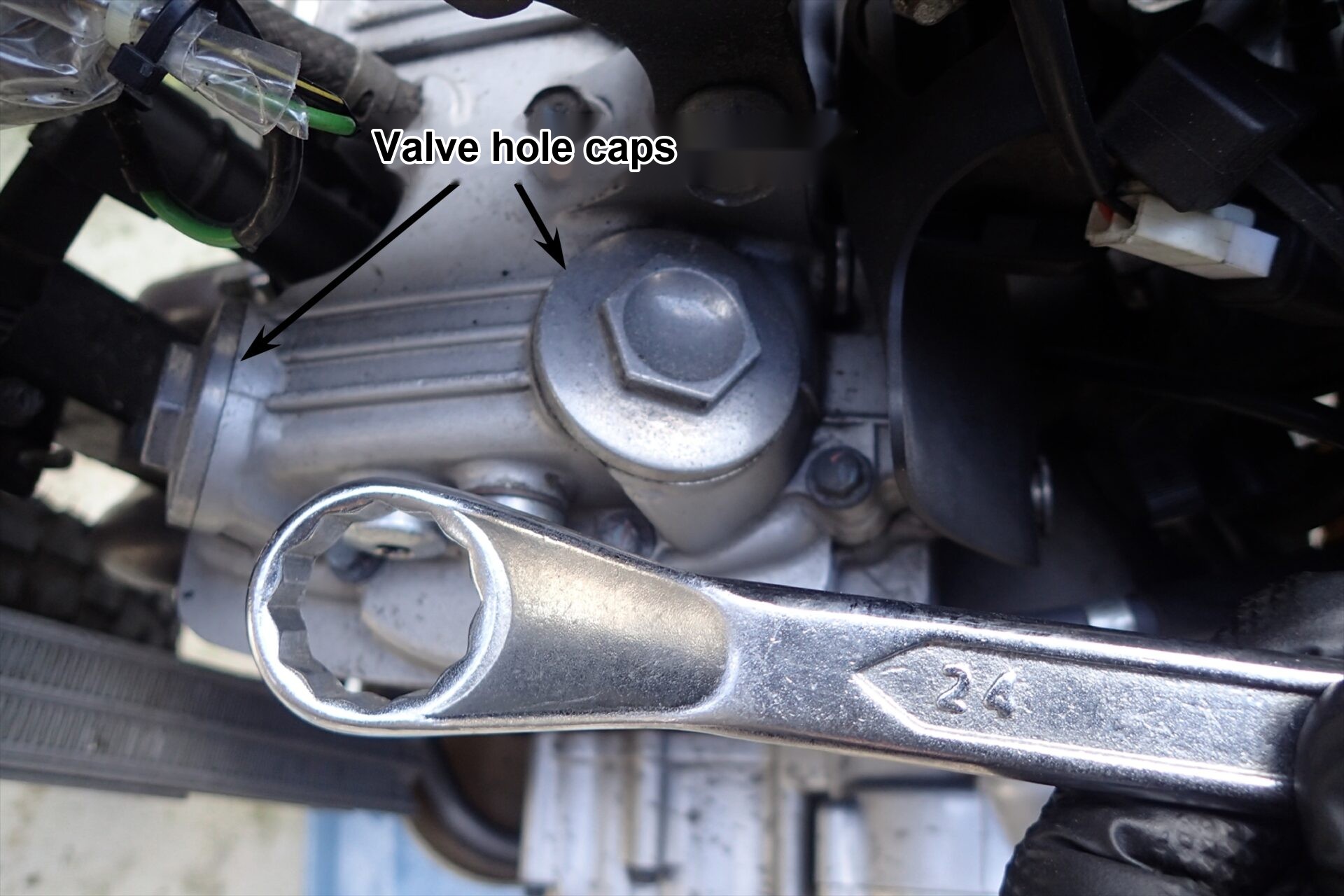
You need a 24 mm spanner (wrench) to remove the valve hole caps.
Some of the caps are awkward to remove because the engine hanger gets in the way.

Remove the valve hole caps.
If you're worried about dirt getting in through the holes, don't remove all the caps at once: remove one cap, adjust that clearance, then move on to the next cap, and repeat.
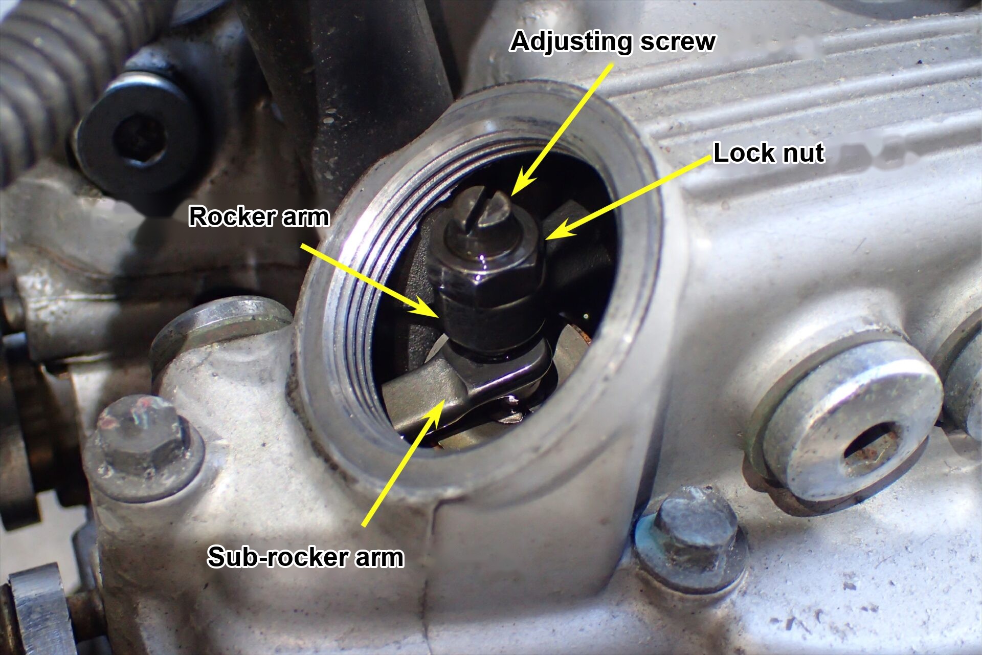
With the cap off, you can see the adjusting screw and lock nut used to adjust the tappet clearance.
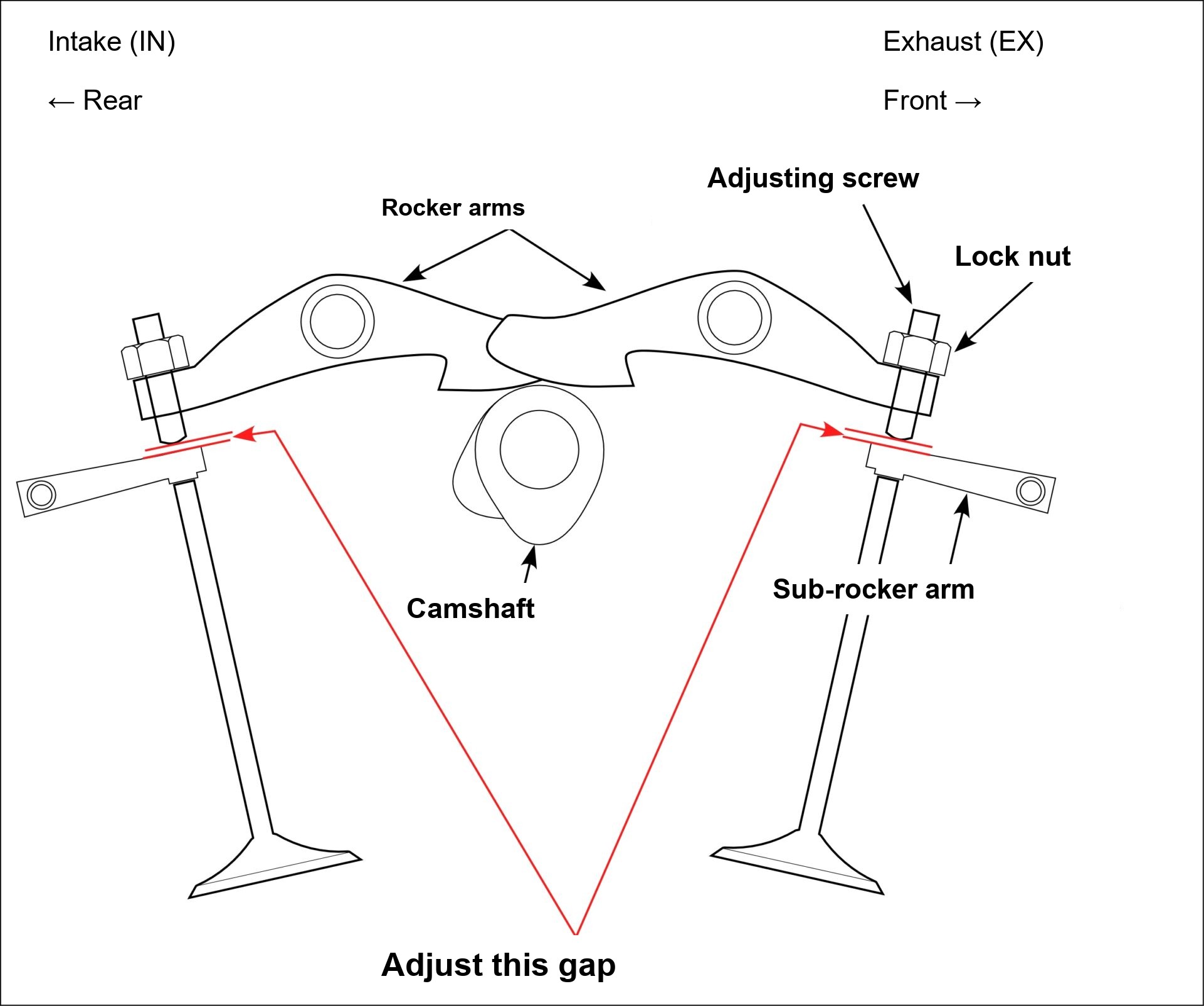
I've drawn a diagram to make it (hopefully) easier to understand.
Adjusting the clearance means setting the gap shown by the red lines in the diagram to the specified value.
Specified valve clearance
IN (intake): 0.10 ± 0.02 mm (0.08 to 0.12 mm)
EX (exhaust): 0.12 ± 0.02 mm (0.10 to 0.14 mm)

The photo above shows the left-hand exhaust valve (as seen facing the direction of travel).
Measure the gap by inserting a feeler gauge.
If the feeler gauge goes in, the clearance is bigger than that gauge.
On the other hand, if the gauge doesn't go in, you can't tell what the clearance is.
I've heard that the clearance equals the gauge thickness when sliding the gauge in feels like "cutting yokan" (a firm Japanese sweet bean jelly).
If you've never cut yokan, that won't help, but it's a feeling where the gauge slides in smoothly, neither tight nor loose.

To adjust the clearance you need a flat-blade screwdriver to turn the adjusting screw, and a spanner to turn the lock nut: 10 mm on the IN side and 12 mm on the EX side.
Adjust the gap with the adjusting screw and measure the clearance with the feeler gauge. If the reading is out of spec, adjust it again with the adjusting screw.
That's the process.

Once the clearance adjustment is done, refit the valve hole caps.

After refitting all four valve hole caps, refit the timing hole cap and the crankshaft hole cap.
All that's left is to refit the fuel tank and seat removed in the preparation part.